Use Jobs to keep each customer job’s source artwork, cleaned artwork and generated files together. Start here when you want a local history of production work, then choose the tool needed for the artwork.
Available with Pro in the desktop app. Job history and files are stored on this computer.
Workflows
Choose the outcome you need and follow the steps in order.
Create a job and generate letters
For artwork that is already ready to build.
Open Jobs and select Upload artwork & create job.
Choose a vector PDF or SVG and confirm the new active job.
Select Generate letters & skip cleanup.
Choose construction, profile and dimensions in Letter generator, then inspect the preview.
Select Generate workshop files and check the resulting files in the active job’s folder.
Result: The source artwork is copied into the job folder and the generated deliverables are recorded against the active job.
Create a job and clean the artwork first
For a vector PDF that needs simpler paths or bend-radius preparation.
Create a job from the PDF, or select Use this job on an existing entry.
Select Clean up artwork.
Adjust cleanup settings and select Export cleaned PDF.
Open and review the cleaned PDF, then select Use cleaned artwork for letter generator.
Configure the letter and generate workshop files.
Result: The job retains its original source and cleaned artwork alongside the generated files.
Prepare letter-bender contours
For face and return outlines without creating a 3D model.
Create or activate a job containing vector PDF artwork.
Select Letter-bender offsets.
Enter face/return contour groups and labels.
Create the contour PDF directly, or clean the PDF first if needed.
Open Contour PDF and compare its offsets and dimensions with your workshop requirements.
Result: A contour PDF is written into the active job’s artwork workflow folder.
Return to an earlier job
For continuing production or locating previous deliverables.
Find the job in Job history using its name, dates and status.
Select Use this job to activate it.
Use Open folder or Re-open last files to inspect the recorded outputs.
Choose the required workflow and check its artwork input before producing new files.
Result: Further work uses the selected active job. Renaming or deleting history entries is explained below.
Jobs is the Pro workspace for organising local artwork, workflow stages and generated files. Job history belongs to this computer; it is separate from a saved project file.
How to use it
Open Jobs and create a job from your artwork.
Choose Clean up artwork, Letter-bender offsets, or Generate letters & skip cleanup.
Activate a listed job to work on its setup; inspect its status and recorded files.
Use Open folder or the reopen-files action to access prior results.
Use Rename to change the project name. Review the deletion prompt before deleting a job.
Active jobs route cleaned artwork and workshop exports to their job folders. Check the displayed destination before generating.
If the job index cannot be read or saved, resolve the folder/permission warning before relying on history. Browser previews cannot manage local job folders.
Keep a separate backup of artwork and deliverables you need to retain.
Job history, folders and actions
Upload artwork & create job copies the selected PDF or SVG into a local job folder named from the artwork. Job history shows Name, Created, Updated and Status so you can find earlier work. The active job is the destination for subsequent workflow outputs.
How to use it
Select Use this job beside a history entry to make it active. The active row shows Active.
Select Open folder to inspect its source artwork and deliverables, or Re-open last files to open its recorded results.
Select Rename, enter Project name and select Save name to change the history label.
Select Delete and review the prompt. Select Delete project to remove the history entry, or Cancel to keep it.
Renaming changes the history label; existing folder and file names stay the same.
Deleting a job from Jobs leaves its artwork and generated files in the folder. Keep backups of files you need.
A job status describes the last recorded activity. Open the files and check the completion message before using a result for production.
Use Artwork Cleanup to simplify PDF outlines, control small corners and bend radii, reuse presets, and prepare contour-offset PDFs. Choose whether to clean first or apply offsets directly to the original artwork.
Available with Mid and Pro. Cleanup and contour export require vector PDF; SVG can go directly to letter generation.
Workflows
Choose the outcome you need and follow the steps in order.
Clean a PDF for letter generation
For improving the outlines before building a letter.
Open Artwork Cleanup and select a vector PDF using Browse or the drop area.
Choose a preset or set Denode strength, Corner threshold and Minimum radius.
Choose the export destination and select Export cleaned PDF.
Open cleaned PDF and inspect the result, including any skipped-path warnings.
Select Use cleaned artwork for letter generator to continue with the cleaned result.
Result: A new cleaned PDF is created. The original remains available and the generator uses the cleaned file only after the handoff.
Clean and export contour offsets
For a cleaned source plus face/return cutting outlines.
Select a PDF and adjust the cleanup settings.
Enter comma-separated offsets and labels for each contour group.
Select Export cleaned PDF.
Select Create Contour PDF to apply the groups to the cleaned result.
Open Contour PDF and verify outer outlines, counters and labelled groups.
Result: You have a cleaned PDF and a separate contour PDF based on the cleaned artwork.
Apply offsets without cleanup
For preserving existing curves while preparing additional contours.
Choose the original vector PDF.
Set the contour groups and labels.
Confirm the output folder.
Select Skip cleanup & apply offsets.
Open Contour PDF and check the result.
Result: Contour offsets are applied to the original artwork without denoding or radius correction.
Save a reusable cleanup preset
For repeating the same preparation settings across jobs.
Set cleanup values, contour offsets and group labels.
Enter a Preset name and select Save preset.
On the next PDF, choose that name from Named preset.
Review the applied values and export a sample result.
Result: The preset is stored on this computer. Saving the same name updates it; Delete preset removes it.
Artwork Cleanup simplifies vector PDF paths and adjusts small curves for fabrication. SVG can go directly to generation, but cleanup requires PDF. Cleanup writes a new file and leaves the original intact.
How to use it
Open Artwork Cleanup and choose a vector PDF.
Set Denode strength (0–1): higher values remove more redundant nodes; the default is 0.15.
Set Corner threshold in millimetres: micro-curves below this threshold may become corners; the default is 2 mm.
Set Minimum radius in millimetres: this controls the minimum bend radius; 0 skips this adjustment and the default is 10 mm.
Choose an export folder, select Export cleaned PDF, and open it to compare with the original before using the cleaned artwork for generation.
If paths or corrections were skipped, review the report and compare the result with the original. Reduce aggressive settings if important details changed.
Named presets store cleanup values, contour groups and labels on this computer. Enter a name and select Save preset; saving the same name updates it. Choose a saved preset to apply it, or Delete preset to remove it.
Exporting a cleaned PDF does not automatically replace the generator input. Use the cleaned-artwork action offered below the export, or open the exported PDF in the generator. Skip to 3D letter generation keeps the uploaded artwork.
Contour PDFs and letter-bender offsets
Contour offsets create additional outlines at specified distances from the artwork for face and return preparation. Groups are stacked in the contour PDF and can have separate labels. Positive and negative distances offset in opposite directions; inspect outer boundaries and counters in the exported PDF.
How to use it
Enter comma-separated millimetre offsets for each group, such as 0, 1.6 or -0.6.
Name the groups for their workshop purpose, such as Face or Return. Use Add offset group or Remove as needed.
To use cleaned artwork, export the cleaned PDF first and select Create Contour PDF.
To use the original artwork directly, select Skip cleanup & apply offsets. In the Jobs workflow, Letter-bender offsets also allows direct contour export.
Open Contour PDF and verify each group before cutting or bending.
The top cleaned artwork remains at 0 mm. An offset value is a contour distance, not letter depth.
Use valid numbers, with at most 20 offsets per group and 99 total. Contour export requires PDF and an output folder.
Without a chosen export folder, cleanup can use the artwork folder. An active Job stores cleaned artwork in its own artwork folder.
Choose which artwork goes to the generator
Cleanup produces a new PDF. The generator continues using the uploaded artwork until you explicitly select the cleaned result. Contour PDFs are separate workshop outputs for offsets.
How to use it
Select Export cleaned PDF to create the cleaned result.
Select Open cleaned PDF and compare the outlines, counters and dimensions with the original.
Select Use cleaned artwork for letter generator to switch the generator input to that result.
If you want the original instead, select Skip to 3D letter generation.
Check the Artwork path in the generator before building the model.
Create Contour PDF uses an available cleaned result; Skip cleanup & apply offsets applies the contour groups directly to the original PDF.
If cleanup reports skipped paths or corrections, inspect the exported PDF before accepting it. An export alone does not confirm every correction succeeded.
Use Letter generator to turn PDF or SVG artwork into letter geometry and workshop files. Work through artwork, construction, preview and export. Save the project when you need to resume the setup later.
Starter includes the basic generator with Profile 1; wider profile access and additional workflows depend on your plan. Generation runs locally in the desktop app.
Workflows
Choose the outcome you need and follow the steps in order.
Generate a letter set from artwork
The complete path from vector artwork to workshop files.
Select Open artwork, wait for analysis and verify the dimensions and Import scale.
Choose Front, Halo, Solid or a shaped-face construction and an available profile.
Set depth and profile dimensions, then configure supported mounting and wire holes.
Inspect the current preview using camera views, Section and Exploded view.
Choose Export folder, select Generate workshop files and inspect the completion status and artifacts.
Result: The artifact list identifies the workshop files actually written. Open or Show in folder provides access to each result.
Create a rounded, bevelled or bubble face
For letters with a shaped front surface.
Import outlined artwork and check its size.
Choose Rounded Face, Bevelled Face or Bubble.
Set Depth and the corresponding Dome amount, Bevel amount or Inflation percentage.
Choose No halo or Halo and inspect the rebuilt preview.
Generate workshop files and check the output geometry.
Result: The shaped-face model uses the chosen face style and halo option. STEP is unavailable for this construction.
Review and adjust drilling holes
For supported profiles needing customised mounting or wire positions.
Configure Mounting and wire holes and wait for the current layout.
LetterForge turns vector artwork into local fabrication files. The desktop app analyses and generates on your computer; the website manages your account and provides this guide. Feature availability depends on your plan and installed version.
How to use it
Sign in to the Windows desktop app with your LetterForge account.
Select Open artwork and choose a vector PDF or SVG with lettering converted to outlines.
Check the analysed dimensions and components, then choose the construction and an available profile.
Inspect the preview and choose an Export folder.
Select Generate workshop files. Wait for completion and open the resulting files from the export list.
A browser preview of the desktop interface cannot run the native local worker. Use the installed app for analysis, cleanup and generation.
Review the output dimensions, fit and material allowances before fabrication. A successful export means files were written; it does not verify your printer or workshop process.
Import artwork and check its size
PDF and SVG are supported for letter generation. The artwork must contain vector outlines; a scanned image or photograph does not supply usable letter contours. Counters are enclosed openings such as the centre of an O.
How to use it
Convert live text to outlines in your drawing program and export a vector PDF or SVG.
Use Open artwork, Browse, the drop area, or the Artwork path field to select a local file.
Wait for analysis and read Size, Tallest, Components and any warnings.
Choose Import scale: 1:1 keeps the source size; 2:1, 5:1 and 10:1 multiply it.
Check that outlines and counters appear correctly before continuing.
Components describe the detected artwork shapes, which may include separate punctuation or disconnected pieces rather than one component per word.
Changing a path or scale triggers analysis and can make an existing preview out of date. If analysis fails, check the path, export outlined artwork again, and retry.
Choose construction and face shape
Construction selects the type of letter; the profile controls its cross-section and assembly features. Only compatible profiles appear for the selected construction.
How to use it
Choose Front for a front-lit construction, Halo for a rear-lit construction, or Solid for a filled letter.
Choose Rounded Face, Bevelled Face or Bubble for shaped-face letters. Set Dome amount, Bevel amount or Inflation percentage respectively.
For shaped-face letters, choose No halo or Halo as required.
Set Depth in millimetres from the available choices and select an allowed profile where the profile picker is shown.
Inspect the preview after changing construction; resolve all construction warnings before generating.
Depth is the front-to-back dimension, not artwork height. Fixed-depth profiles lock the depth selector.
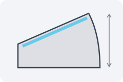
For supported Front profiles, enable Angle face, set Face rise and choose Deeper toward Top, Right, Bottom or Left. Rise is measured across the largest character in that direction; all characters use the same angle.
The curved-back, straight-face profile uses Total height above base and Face angle above base (0–75°). Height can increase automatically to fit the angle and face seat.
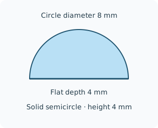
The rounded-outline profile sweeps a circular section around outer outlines and counters. Circle diameter controls the section; Flat depth from back removes its back portion. An 8 mm circle with a 4 mm flat makes a 4 mm-high semicircle.
Profile dimensions and fit allowances
Open Profile dimensions for the selected profile’s available controls. Values are in millimetres unless marked as degrees or percentages. Controls differ by profile because their assemblies differ.
How to use it
Select the profile using its cross-section picture and label.
Open Profile dimensions and adjust the controls exposed for that profile.
Inspect the updated geometry, including internal seats and separate components.
Generate a sample and check the physical fit before applying new allowances to a full production set.
Wall controls shell thickness. Bottom controls back/base thickness where used. Face controls the face material or seat thickness. Ledge controls the supporting seat width.
Face gap allows clearance at the face fit. Nest gap allows clearance between nested parts. Inner face offset shifts an inner face contour. Back inset sets an inset at the back. Return width controls the return section where present. Light tray controls the tray dimension where present.
Tray inline contour is the contour allowance for tray preparation. Keep allowances consistent with the material, cutting process and fit you have tested.
Profile defaults can be edited in Settings. Project controls override values for the current setup; not every profile exposes every dimension.
Mounting and wire holes
Supported profiles expose mounting holes and one optional wire hole per entity. These controls are unavailable for shaped-face/bubble construction. Hole placement depends on the available material in each letter.
How to use it
Open Mounting and wire holes and enable mounting holes if needed.
Set Mounting holes per entity; 0 uses automatic placement. Set the mounting-hole diameter.
Set the mounting-hole offset from centreline to shift centres across the local stroke.
Enable one wire hole per entity, choose its diameter and location (Top, Right, Bottom or Left), and set its offset.
Generate and read placement warnings, then inspect the output hole locations.
Offsets are in millimetres. Positive values move toward the right or top; for wire holes this means right at top/bottom locations, and top at left/right locations.
Holes that cannot fit safely are reported during generation. If a hole cannot fit, reduce its diameter or offset, change the count or construction, and inspect the next result.
Edit hole placement and review imported holes
Edit hole placement / review imported holes opens a rear drilling layout. Blue circles are mounting holes, orange circles are wire holes, and numbered circular outlines identify imported candidates. The X/Y coordinates and diameters are in millimetres; positive Y points upward.
How to use it
Open the editor and wait for the current layout to become ready.
Drag a hole to move it, or select it and enter X, Y and Diameter. Arrow keys move a selected hole by 0.5 mm; Shift changes the step to 5 mm.
Select Add mounting hole or Add wire hole, then click inside an entity. Delete selected hole removes the selected placement; Reset automatic layout discards manual placements.
Under Review imported circular holes, classify each circle as Letter counter / keep in artwork, Mounting hole / remove from faces, or Wire hole / remove from faces. Select Apply reviewed holes.
Use Save placements to retain the layout or Load placements to restore one for the same artwork. Close the editor and inspect the regenerated preview before exporting.
Keep the full hole inside the supported placement region and clear of edges and counters. The editor requires at least 1 mm between holes and allows only one wire hole per entity.
A circular opening may be part of the letter design. Candidates remain counters until you classify and apply the review; check letters such as O before removing a circle from face artwork.
Placements are associated with the artwork and construction/profile. Loading placements for different artwork is rejected. Read the save status before relying on a saved layout.
Navigate and inspect the 3D preview
The viewport helps you inspect the letter geometry. A draft preview is provisional; the local worker produces the generated mesh. Status messages identify builds, outdated previews and failures.
How to use it
Drag to orbit the model and scroll to zoom. Use the viewport’s pan gesture to move the view.
Use Iso, Front or Back for preset views; Reset restores the camera framing.
Enable Section and move its slider to inspect a cross-section.
Move Exploded view to separate assembly parts visually.
Wait for preview building to finish and check the status before judging changed settings.
Section and Exploded view are inspection tools; they do not change your exported construction.
After changing settings, an older mesh may remain visible while rebuilding. Workshop export uses the current construction settings, not the stale preview. If rebuilding fails, read the error and correct the input.
Generate and open workshop files
Generate workshop files runs the local geometry worker and writes the outputs supported by the construction. The artifact list is the record of files actually produced.
How to use it
Confirm artwork analysis succeeded, construction values are valid and your plan permits the operation.
Choose a writable Export folder.
Select Generate workshop files and follow the progress and warning messages.
Use Open on a result to launch its associated program, or Show in folder to locate the file. Open export folder opens the result directory.
If available on your plan, select Generate STEP separately when you need an editable CAD exchange model.
STL contains mesh geometry for printing or mesh tools. STEP contains CAD geometry for compatible CAD software. PDF contains 2D workshop contours. DXF contains vector paths for compatible cutting or CAD tools, including separate backs on profiles that require them. Available files depend on the selected construction; use the displayed artifact types and filenames.
STEP is unavailable for bubble/shaped-face letters. It is a separate generation action and can take additional processing.
Cancel generation, Cancel STEP or Cancel preview stops the active operation. Partial files may exist; check the final status before treating an export as complete.
If an export fails after a preview was created, the preview does not mean the full workshop export succeeded. Read the error and verify the requested artifacts exist.
Save, reopen and recover projects
Project files preserve the working setup so you can resume later. They reference local artwork and outputs; keep those files available when moving or reopening a project.
How to use it
Select Save project and choose a project filename.
Use Save As to create a separate saved version.
Use Open project to restore a saved setup and check any missing-file warnings.
Use New project to begin a fresh setup; save work you want to keep first.
The app also keeps a local recovery record. Treat recovery as a convenience, and save named project files for work you need to retain.
If referenced artwork was moved, select its new location. Read save errors: a visible setup is not proof that the file was saved.
Settings and reusable defaults
Settings stores defaults and local folder preferences on this computer. It includes dimensions, construction/profile defaults, halo behaviour and advanced folder choices.
How to use it
Open Settings and expand the section you want to edit.
For profile defaults, choose Profile to edit and change its available dimensions.
Set default construction, depth, bubble depth and other dimensions as needed. Max height controls the configured height limit; it does not enlarge artwork.
Use Browse to select default artwork and export folders.
Check Settings saved on this computer. Use Apply to this project to replace the current project’s working defaults, or Close when finished.
Reset factory restores factory defaults. Save the current project before applying broad changes you may want to undo.
Default depths must be compatible with the selected construction. Bubble halo can be locked to Profile 1. Fixed profiles retain their fixed catalog dimensions.
A save warning means the changed defaults were not persisted. Correct the storage issue and confirm the saved message.
Profile reference
Match the number and cross-section picture to the picker in Letter generator. Available profiles depend on construction and plan. Each card describes the catalog’s assembly; inspect its dimensions before exporting.
Profile 1
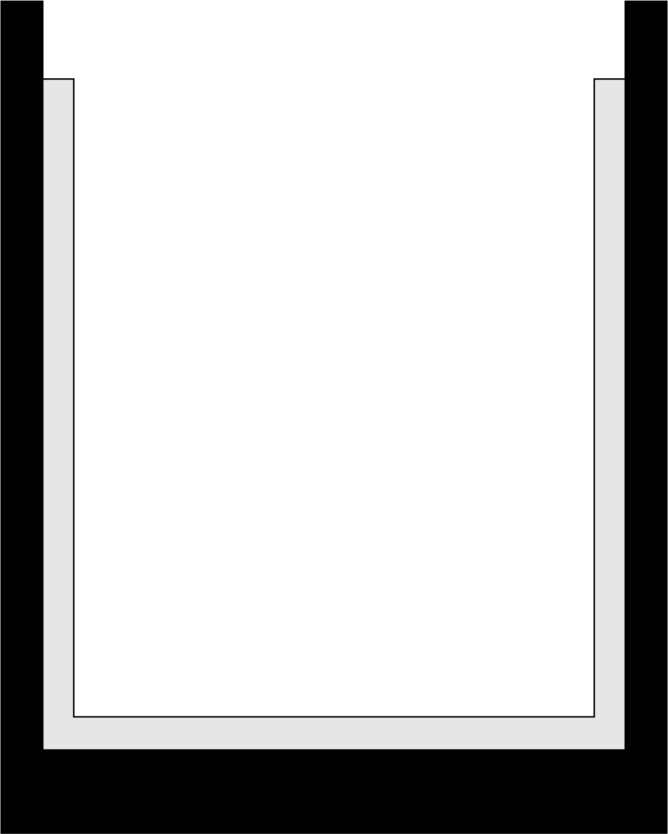
Open-backed outer + light tray
Profile 2
Straight outer + inner tray
Profile 3
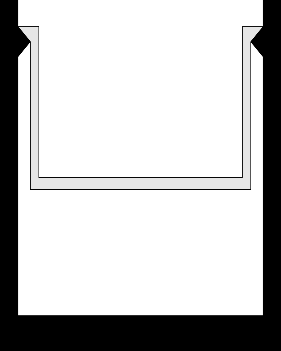
Ledge-free shell + reversed tray
Profile 4
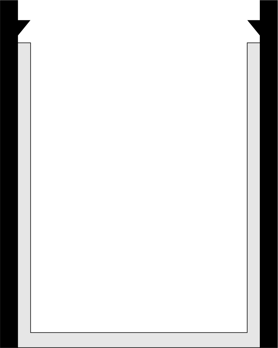
Backed outer with triangle ledge + nested cup with chamfered outer seat
Profile 5
Single backed body + acrylic ledge
Profile 6
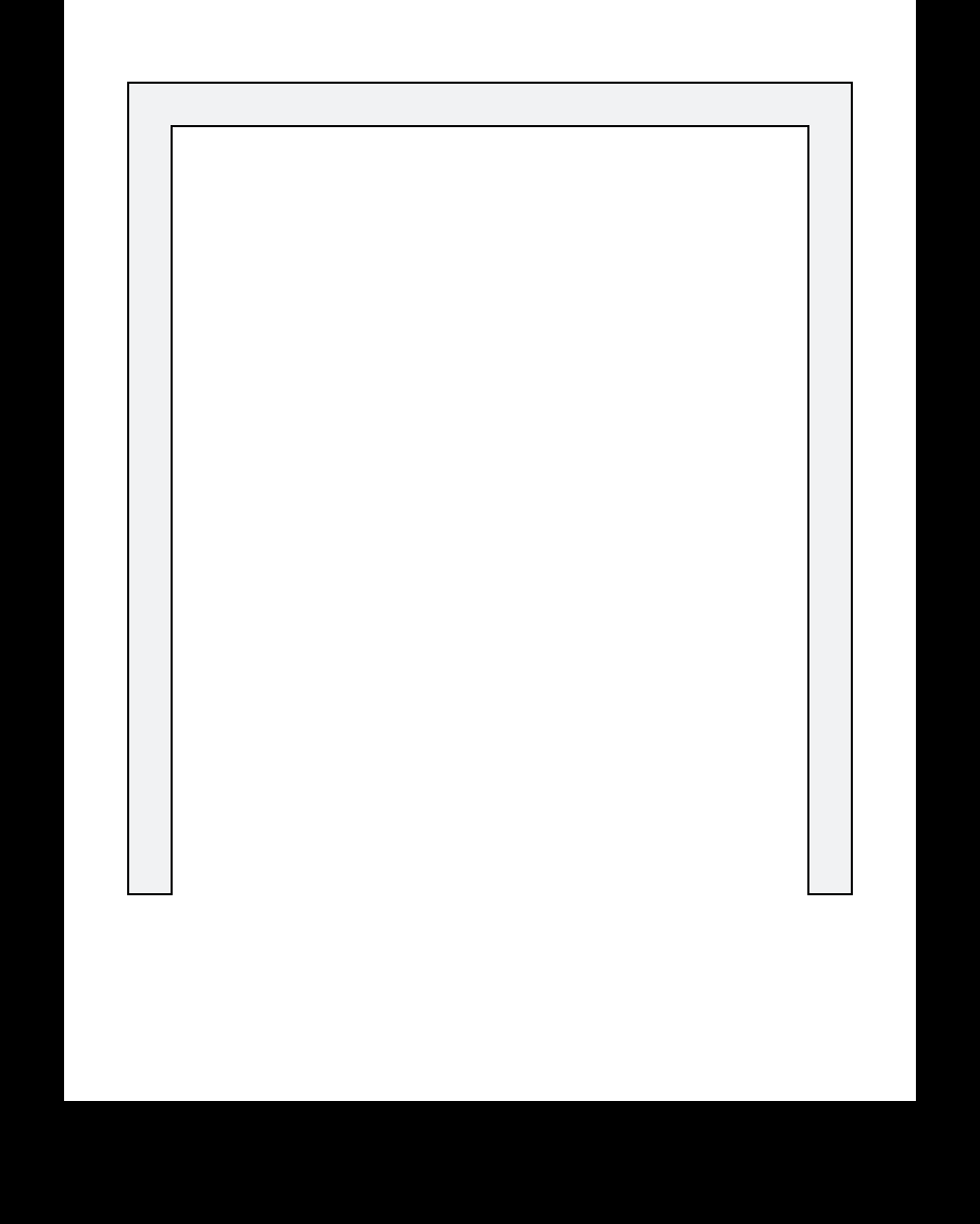
Backed outer with straight sides and no face ledge
Profile 7
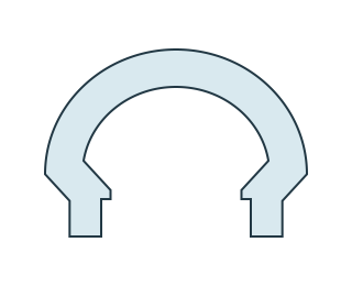
Open back + chamfered face seat; separate back DXF
Use LetterLoop to repeat an already sliced print plate or sequence with a tested FarmLoop Stage 1 auto-unload setup. Prepare and test the printer preset before creating a chain.
Available with Pro in the desktop app. Input must be a plate-sliced Bambu .gcode.3mf file.
Workflows
Choose the outcome you need and follow the steps in order.
Prepare the printer and auto-unload preset
One-time preparation for your exact printer and hardware.
Check the supplier’s compatibility guide and install the matching Stage 1 hardware.
Expand Auto-unload block and select Copy auto-unload G-code.
Insert the block after filament retraction/unload and before final parking or motor shutdown in your existing End G-code.
Save a separate preset and re-slice the test plate.
Run a supervised test and confirm the parts release, clear the plate and leave the machine ready for the next print.
Result: You have a tested auto-unload preset. Preserve the ordinary printing preset for jobs that do not use the unload hardware.
Repeat one sliced plate
For producing several runs of the same plate.
Slice using the tested preset and export with File → Export → Export plate sliced file in Bambu Studio.
Select Choose sliced file in LetterLoop and choose the .gcode.3mf.
Choose output folder and set Plate / sequence repeats from 1–99.
Confirm the tested-unload condition and select Create print chain.
Wait for completion and select Show in folder to locate the result.
Result: A print-chain file repeats the selected plate using its existing sliced instructions.
Repeat a multi-plate sequence
For printing an ordered batch with matching machine and filament settings.
Prepare and test every plate with the auto-unload preset and matching machine/filament settings.
Export the plate-sliced multi-plate file.
Choose the file and output folder in LetterLoop.
Set repeats for the whole sequence, confirm the unload test and create the chain.
Check the completion message and saved result.
Result: Plates run in their stored order and the whole sequence repeats. AMS remapping is not supported.
LetterLoop is the Pro print-chain tool for plate-sliced Bambu .gcode.3mf files prepared with a tested FarmLoop Stage 1 auto-unload preset. It repeats your sliced sequence and preserves existing Start/End G-code; it does not add ejection moves.
How to use it
Use the supplier’s Stage 1 instructions and compatibility guide to install hardware for your exact printer. Check pusher, plate and travel clearances.
Copy the app’s auto-unload block into your existing End G-code after filament retraction/unload and before final parking or motor shutdown. Preserve the other routines and save a separate printer preset.
Run a supervised test and confirm the finished parts release and the plate clears. Re-slice using this tested preset.
In Bambu Studio, use File → Export → Export plate sliced file. In LetterLoop, choose the resulting .gcode.3mf and an output folder.
Set Plate / sequence repeats to an integer from 1–99, confirm the tested auto-unload condition, and select Create print chain. Use Show in folder for the result.
For multiple plates, the whole sequence repeats in plate order. Filament and machine settings must match across plates; AMS remapping is not supported.
The supplied block uses fixed travel ranges X30–220, Y0–250 and Z200–235 mm, with a sweep height of at least 5 mm. Check these against your hardware. The slicer must support max_layer_z and max() expressions.
Cancel conversion stops an active conversion. A normal unsliced .3mf project is not a plate-sliced .gcode.3mf.
The Functions panel provides the auto-unload block and conversion controls. Choose sliced file selects an already sliced .gcode.3mf; Choose output folder selects where the generated print chain is saved.
How to use it
Expand Auto-unload block to view the supplied code. Copy auto-unload G-code copies it for insertion into your printer preset.
Choose the plate-sliced file. Selecting a different file clears the previous result and tested-unload confirmation.
Set Plate / sequence repeats: a single plate repeats that many times; a multi-plate file repeats the whole ordered sequence.
Tick the confirmation only after slicing with your tested auto-unload preset. Select Create print chain and follow the status message.
Use Show in folder after completion. Cancel conversion stops an active conversion; check completion before using its output.
Create print chain requires the desktop app, a .gcode.3mf input, an output folder, a whole-number repeat count from 1–99 and the tested-unload confirmation.
LetterLoop retains Start/End G-code and AMS metadata. It does not insert ejection moves or remap AMS assignments. All plates must use matching machine and filament settings.
Account shows your subscription and sign-in state. The desktop reads feature access from your account; some controls remain locked until the access check completes.
How to use it
Open Account to inspect your plan, status and billing details.
Use the account or upgrade link to manage your subscription on the website.
If access is missing or expired, sign in again and retry the account check.
Choose the update channel offered by your account if you need to change update preferences.
Starter provides the basic generator with Profile 1. Mid adds Artwork Cleanup and the wider profile catalog. Pro adds Jobs and LetterLoop. Check Pricing and your account for the current offer and available features.
An offline badge indicates cached account access. Cached access can expire; reconnect and sign in if required. Artwork processing still runs locally.
Subscription changes, payment details and account recovery are managed on the website. Use Forgot password on the sign-in screen when needed.
Check for app updates
The header’s update control checks the release channel selected for your account. Update status tells you whether a release is available or the check failed.
How to use it
Save your project and finish active generation or conversion work.
Use the header update control to check for updates.
Follow the offered download/install action and restart when prompted.
If the check fails, verify your connection and retry; a failed check does not confirm that your app is current.
Update controls can be disabled while the app is busy or has unsaved work. Read the displayed reason and save or finish the operation first.
Troubleshooting common problems
Use the first relevant check below. Preserve the exact error message if the issue continues.
How to use it
Artwork rejected or empty: choose PDF/SVG, confirm it contains vector outlines rather than raster images, and check its local path.
Generate disabled: wait for account and artwork analysis, choose an output folder, and resolve construction warnings or plan restrictions.
Cleanup disabled: use PDF, check the output folder and validate contour numbers. SVG can go straight to letter generation.
Preview or export failed: read the worker error, confirm the artwork is accessible and the export folder is writable, then retry in the installed desktop app.
Missing files or account access: reopen/reselect moved local files, or reconnect and sign in for an account check. Use the reporting tool if the error repeats.
For LetterLoop, check the .gcode.3mf suffix, integer repeat count, output folder and tested-unload confirmation. Check plate machine and filament compatibility if conversion fails.
For poor fit, compare import scale and profile allowances with your source dimensions. Check a small sample before re-exporting a full set.
Report a bug or request a feature
Use Report bug / Request feature in the desktop app to send a report linked to your account. Help & Support opens this guide in your browser.
How to use it
Sign in, then open Report bug / Request feature.
Choose the report type and category and enter a short title.
Describe what you were doing, the steps to reproduce, what you expected and what happened. Include the exact error for a bug.
Review the captured screenshot, active artwork attachment and app error log. Remove or replace attachments and edit the log as needed.
Send the report and wait for confirmation. For a profile feature request, include a sketch when useful.
The report tool can prepare a screenshot and attach active artwork automatically. Review them before sending. Reports and attached logs/files are stored for support and emailed to the administrator.
You can submit without screenshot or artwork. Files are limited to 5 MB each and 8 MB total. If the session expired, sign in again; if the daily report limit is reached, retry the next day.
Website account support is also available through the account page’s existing reporting tool.